linkRendering
linkProblem Statement
Visualize some visual computing algorithm
linkBackground
Many rendering algorithms have been researched, and software used for rendering may employ a number of different techniques to obtain a final image.
Tracing every particle of light in a scene is nearly always completely impractical and would take a stupendous amount of time. Even tracing a portion large enough to produce an image takes an inordinate amount of time if the sampling is not intelligently restricted.
Therefore, a few loose families of more-efficient light transport modelling techniques have emerged like rasterization, including scanline rendering, geometrically projects objects in the scene to an image plane, without advanced optical effects.
linkRasterization

Rasterization (or rasterisation) is the task of taking an image described in a vector graphics format (shapes) and converting it into a raster image (a series of pixels, dots or lines, which, when displayed together, create the image which was represented via shapes.
A common representation of digital 3D models is polygonal. Before rasterization, individual polygons are broken down into triangles, therefore a typical problem to solve in 3D rasterization is rasterization of a triangle. Properties that are usually required from triangle rasterization algorithms are that rasterizing two adjacent triangles (i.e. those that share an edge)
- leaves no holes (non-rasterized pixels) between the triangles, so that the rasterized area is completely filled (just as the surface of adjacent triangles). And
- no pixel is rasterized more than once, i.e. the rasterized triangles don't overlap. This is to guarantee that the result doesn't depend on the order in which the triangles are rasterized. Overdrawing pixels can also mean wasting computing power on pixels that would be overwritten.
This leads to establishing rasterization rules to guarantee the above conditions. One set of such rules is called a top-left rule, which states that a pixel is rasterized if and only if
- its center lies completely inside the triangle. Or
- its center lies exactly on the triangle edge (or multiple edges in case of corners) that is (or, in case of corners, all are) either top or left edge.
A top edge is an edge that is exactly horizontal and lies above other edges, and a left edge is a non-horizontal edge that is on the left side of the triangle.
linkOrthographic projection
is a means of representing three-dimensional objects in two dimensions. It is a form of parallel projection, in which all the projection lines are orthogonal to the projection plane, resulting in every plane of the scene appearing in affine transformation on the viewing surface.
linkPerspective projection
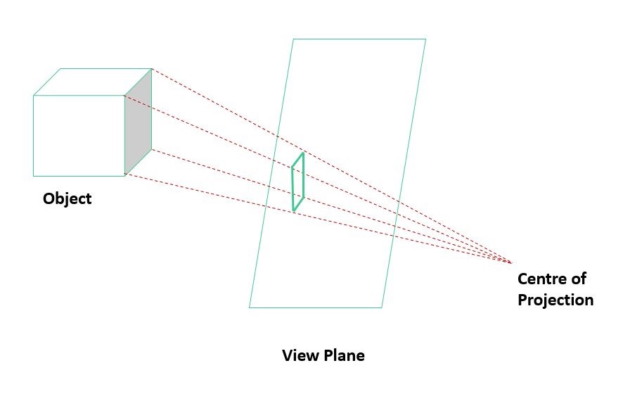
Perspective projection or perspective transformation is a linear projection where three dimensional objects are projected on a picture plane. This has the effect that distant objects appear smaller than nearer objects.

linkSpatial anti-aliasing
spatial anti-aliasing is a technique for minimizing the distortion artifacts known as aliasing when representing a high-resolution image at a lower resolution. Anti-aliasing is used in digital photography, computer graphics, digital audio, and many other applications.
Anti-aliasing means removing signal components that have a higher frequency than is able to be properly resolved by the recording (or sampling) device. This removal is done before (re)sampling at a lower resolution. When sampling is performed without removing this part of the signal, it causes undesirable artifacts such as black-and-white noise.


linkCode and Results
Below is an implementation of rasterization, which allows you to choose between an orthogonal or perspective projection on a plane, and the use of antialising in the representation, as well as the definition of the number of pixels with the bar.
1linklet img;
2linklet count = 0;
3linklet resolution = 10;
4linklet aliasing = false;
5linkconst ALIASING = "antialiasing";
6linkconst PERSPECTIVE = "Perspective";
7linkconst ORTHOGONAL = "Orthogonal";
8linkconst profundidadFocus = -300;
9linkclass Square {
10link constructor(x, y, width) {
11link let point1 = [x, y];
12link let point2 = [x, y + width];
13link let point3 = [x + width, y + width];
14link let point4 = [x + width, y];
15link this.points = [point1, point2, point3, point4]
16link }
17link getPoints() {
18link return this.points;
19link }
20link}
21linkfunction mul(vector, degrees) {
22link let matrixRotation = [[Math.cos(Math.PI * degrees / 180), -Math.sin(Math.PI * degrees / 180)],
23link [Math.sin(Math.PI * degrees / 180), Math.cos(Math.PI * degrees / 180)]]
24link return [vector[0] * matrixRotation[0][0] + vector[1] * matrixRotation[0][1], vector[0] * matrixRotation[1][0] > >+ vector[1] * matrixRotation[1][1], vector[2]]
25link}
26linkfunction traceLine(pointA, pointB) {
27link beginShape(LINES)
28link vertex(pointA[0], pointA[1], pointA[2]);
29link vertex(pointB[0], pointB[1], pointB[2]);
30link endShape();
31link}
32linkfunction tracePoint(point) {
33link beginShape(POINTS)
34link strokeWeight(10);
35link
36link vertex(point[0], point[1], point[2])
37link endShape()
38link}
39link
40linklet projection = PERSPECTIVE;
41linkfunction setup() {
42link createCanvas(720, 540, WEBGL);
43link //img=loadImage('/vc/docs/sketches/lenna.png');
44link ortho(-width / 2, width / 2, -height / 2, height / 2);
45link textureMode(NORMAL);
46link sel = createSelect();
47link sel.option(PERSPECTIVE);
48link sel.option(ORTHOGONAL);
49link sel.changed(changeProjection);
50link sld = createSlider(10, 40, 10, 10);
51link radio = createRadio();
52link radio.option(ALIASING);
53link radio.option('no' + ALIASING);
54link radio.style('width', '20px');
55link
56link}
57linkfunction changeProjection() {
58link projection = sel.value();
59link
60link}
61link
62linkfunction draw() {
63link background(255);
64link count = (count + 5) % 360;
65link cover(true);
66link
67link orbitControl();
68link resolution = sld.value();
69link if (resolution > 20) {
70link frameRate(20);
71link } else {
72link frameRate(40);
73link }
74link aliasing = (radio.value() == ALIASING);
75link}
76link
77linkfunction cover(texture = false) {
78link noStroke();
79link beginShape();
80link
81link
82link let degrees = count;
83link let Acoord = [-width / 4, -height / 4, -10];
84link Acoord = mul(Acoord, degrees)
85link let Bcoord = [width / 4, -height / 4, 80];
86link Bcoord = mul(Bcoord, degrees)
87link let Ccoord = [-width / 4, height / 4, 0];
88link Ccoord = mul(Ccoord, degrees)
89link fill(255, 0, 0);
90link vertex(Acoord[0], Acoord[1], Acoord[2]);
91link fill(0, 255, 0);
92link vertex(Bcoord[0], Bcoord[1], Bcoord[2]);
93link
94link fill(0, 0, 255);
95link vertex(Ccoord[0], Ccoord[1], Ccoord[2]);
96link
97link
98link endShape(CLOSE);
99link beginShape();
100link fill(0);
101link
102link baseCoord = [-200, -240]
103link ancho = 400
104link profundidad = -120
105link vertex(baseCoord[0], baseCoord[1], profundidad);
106link vertex(baseCoord[0], baseCoord[1] + ancho, profundidad)
107link vertex(baseCoord[0] + ancho, baseCoord[1] + ancho, profundidad)
108link vertex(baseCoord[0] + ancho, baseCoord[1], profundidad)
109link endShape(CLOSE);
110link
111link let focus = [(baseCoord[0] * 2 + ancho) / 2, (baseCoord[1] * 2 + ancho) / 2, profundidadFocus]
112link beginShape(POINTS);
113link vertex(focus[0], focus[1], focus[2]);
114link endShape();
115link let dVector_A, dVector_B, dVector_C;
116link if (projection == PERSPECTIVE) {
117link dVector_A = [focus[0] - Acoord[0], focus[1] - Acoord[1], focus[2] - Acoord[2]]
118link dVector_B = [focus[0] - Bcoord[0], focus[1] - Bcoord[1], focus[2] - Bcoord[2]]
119link dVector_C = [focus[0] - Ccoord[0], focus[1] - Ccoord[1], focus[2] - Ccoord[2]]
120link }
121link else if (projection == ORTHOGONAL) {
122link dVector_A = [0, 0, focus[2] - Acoord[2]]
123link dVector_B = [0, 0, focus[2] - Bcoord[2]]
124link dVector_C = [0, 0, focus[2] - Ccoord[2]]
125link }
126link let redFocus = [Acoord[0] + dVector_A[0], Acoord[1] + dVector_A[1], Acoord[2] + dVector_A[2]];
127link stroke(255, 0, 0);
128link traceLine(Acoord, redFocus);
129link let greenFocus = [Bcoord[0] + dVector_B[0], Bcoord[1] + dVector_B[1], Bcoord[2] + dVector_B[2]];
130link stroke(0, 255, 0);
131link traceLine(Bcoord, greenFocus);
132link let blueFocus = [Ccoord[0] + dVector_C[0], Ccoord[1] + dVector_C[1], Ccoord[2] + dVector_C[2]];
133link stroke(0, 0, 255);
134link traceLine(Ccoord, blueFocus);
135link let tA = ((profundidad - Acoord[2]) / dVector_A[2]) - 0.01;
136link let redPoint = [Acoord[0] + tA * dVector_A[0], Acoord[1] + tA * dVector_A[1], Acoord[2] + tA * dVector_A[2]]
137link stroke(255, 0, 0);
138link tracePoint(redPoint);
139link let tB = ((profundidad - Bcoord[2]) / dVector_B[2]) - 0.01;
140link let greenPoint = [Bcoord[0] + tB * dVector_B[0], Bcoord[1] + tB * dVector_B[1], Bcoord[2] + tB * dVector_B[2]]
141link stroke(0, 255, 0);
142link tracePoint(greenPoint);
143link let tC = ((profundidad - Ccoord[2]) / dVector_C[2]) - 0.01;
144link let bluePoint = [Ccoord[0] + tC * dVector_C[0], Ccoord[1] + tC * dVector_C[1], Ccoord[2] + tC * dVector_C[2]]
145link stroke(0, 0, 255);
146link tracePoint(bluePoint);
147link strokeWeight(1);
148link beginShape()
149link fill(255, 0, 0);
150link vertex(redPoint[0], redPoint[1], redPoint[2])
151link fill(0, 255, 0);
152link vertex(greenPoint[0], greenPoint[1], greenPoint[2])
153link fill(0, 0, 255);
154link vertex(bluePoint[0], bluePoint[1], bluePoint[2])
155link endShape(CLOSE)
156link let squares = [];
157link
158link let widthGrid = ancho / resolution;
159link
160link for (let i = baseCoord[0]; i < baseCoord[0] + ancho; i += widthGrid) {
161link for (let j = baseCoord[1]; j < baseCoord[1] + ancho; j += widthGrid) {
162link squares.push(new Square(i, j, widthGrid));
163link }
164link }
165link fill(80, 80, 80);
166link stroke(0);
167link squares.map(sq => {
168link
169link beginShape();
170link let points = sq.getPoints();
171link let barcoord1 = barycentricCoord(points[0], [redPoint[0], redPoint[1]], [greenPoint[0], greenPoint[1]], > >[bluePoint[0], bluePoint[1]]);
172link let barcoord2 = barycentricCoord(points[1], [redPoint[0], redPoint[1]], [greenPoint[0], greenPoint[1]], > >[bluePoint[0], bluePoint[1]]);
173link let barcoord3 = barycentricCoord(points[2], [redPoint[0], redPoint[1]], [greenPoint[0], greenPoint[1]], > >[bluePoint[0], bluePoint[1]]);
174link let barcoord4 = barycentricCoord(points[3], [redPoint[0], redPoint[1]], [greenPoint[0], greenPoint[1]], > >[bluePoint[0], bluePoint[1]]);
175link
176link if (!aliasing || !cointained(barcoord1, barcoord2, barcoord3, barcoord4)) {
177link let avgPoint = [(points[0][0] + points[2][0]) / 2, (points[0][1] + points[2][1]) / 2];
178link let barcoord = barycentricCoord(avgPoint, [redPoint[0], redPoint[1]], [greenPoint[0], greenPoint[1]], > >[bluePoint[0], bluePoint[1]]);
179link fill(255 * barcoord[0], 255 * barcoord[1], 255 * barcoord[2]);
180link vertex(points[0][0], points[0][1], profundidad - 0.3);
181link vertex(points[1][0], points[1][1], profundidad - 0.3);
182link vertex(points[2][0], points[2][1], profundidad - 0.3);
183link vertex(points[3][0], points[3][1], profundidad - 0.3);
184link
185link } else {
186link
187link fill(255 * barcoord1[0], 255 * barcoord1[1], 255 * barcoord1[2]);
188link vertex(points[0][0], points[0][1], profundidad - 0.3);
189link fill(255 * barcoord2[0], 255 * barcoord2[1], 255 * barcoord2[2]);
190link vertex(points[1][0], points[1][1], profundidad - 0.3);
191link fill(255 * barcoord3[0], 255 * barcoord3[1], 255 * barcoord3[2]);
192link vertex(points[2][0], points[2][1], profundidad - 0.3);
193link fill(255 * barcoord4[0], 255 * barcoord4[1], 255 * barcoord4[2]);
194link vertex(points[3][0], points[3][1], profundidad - 0.3);
195link }
196link
197link endShape(CLOSE);
198link });
199link
200link
201link}
202linkfunction cointained(barCood1, barCood2, barCood3, barCood4) {
203link return (barCood1[0] != 1 || barCood1[1] != 1 || barCood1[2] != 1)
204link || (barCood2[0] != 1 || barCood2[1] != 1 || barCood2[2] != 1)
205link || (barCood3[0] != 1 || barCood3[1] != 1 || barCood3[2] != 1)
206link || (barCood4[0] != 1 || barCood4[1] != 1 || barCood4[2] != 1)
207link}
208linkfunction barycentricCoord(p, redPoint, greenPoint, bluePoint) {
209link let v0;
210link let v1, v2;
211link if (count >= 90 && count <= 269) {
212link v0 = redPoint;
213link if ((redPoint[0] > greenPoint[0])) {
214link
215link v1 = greenPoint;
216link v2 = bluePoint;
217link } else {
218link v1 = bluePoint;
219link v2 = greenPoint;
220link
221link }
222link
223link
224link
225link } else {
226link v0 = greenPoint;
227link if (greenPoint[0] > redPoint[0]) {
228link v1 = bluePoint;
229link v2 = redPoint;
230link } else {
231link v1 = redPoint;
232link v2 = bluePoint;
233link }
234link
235link }
236link
237link let f12 = (v1[1] - v2[1]) * p[0] + (v2[0] - v1[0]) * p[1] + (v1[0] * v2[1] - v1[1] * v2[0]);
238link let f20 = (v2[1] - v0[1]) * p[0] + (v0[0] - v2[0]) * p[1] + (v2[0] * v0[1] - v2[1] * v0[0]);
239link let f01 = (v0[1] - v1[1]) * p[0] + (v1[0] - v0[0]) * p[1] + (v0[0] * v1[1] - v0[1] * v1[0]);
240link
241link if (f12 < 0 || f20 < 0 || f01 < 0) {
242link
243link return [1, 1, 1];
244link
245link }
246link let area = f12 + f20 + f01;
247link lambda0 = f12 / area;
248link lambda1 = f20 / area;
249link lambda2 = f01 / area;
250link if (!(redPoint[0] > greenPoint[0])) {
251link if (bluePoint == v1) {
252link return [lambda2, lambda0, lambda1];
253link } else {
254link return [lambda1, lambda0, lambda2];
255link }
256link } else {
257link if (v1 == greenPoint) {
258link return [lambda0, lambda1, lambda2];
259link } else {
260link return [lambda0, lambda2, lambda1];
261link }
262link }
263link
264link
265link}